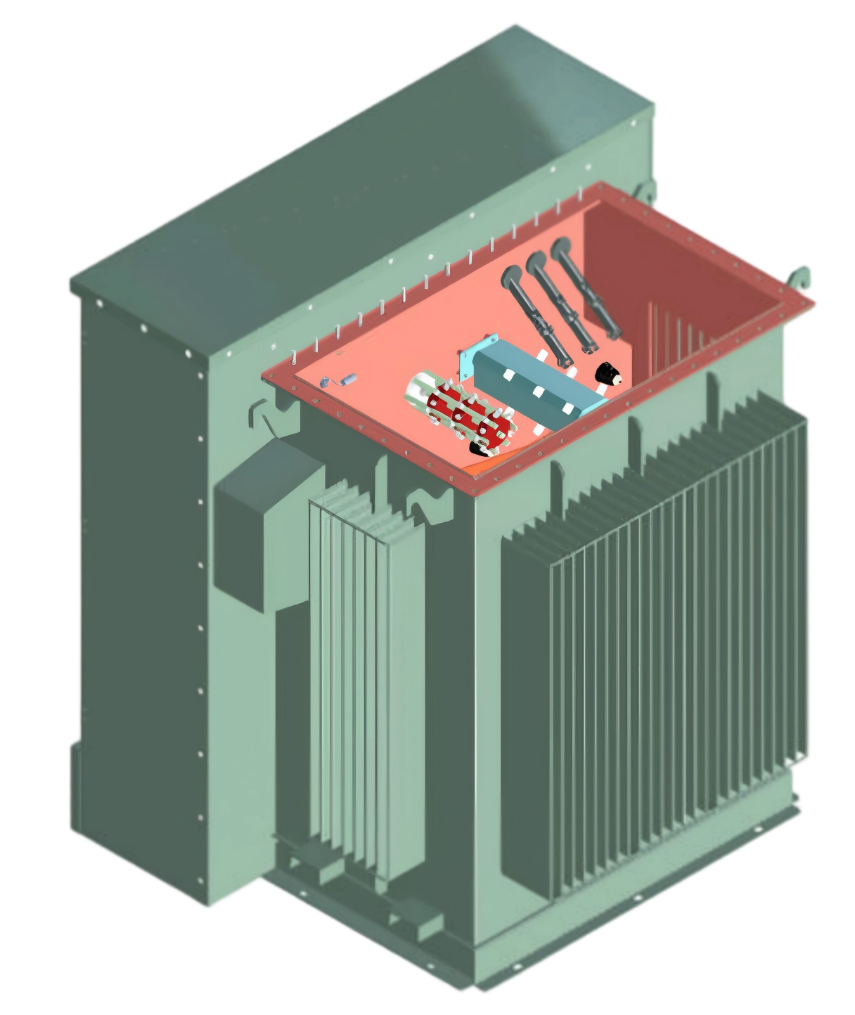
Power Transformer 3D Drawing Automatic Tool To Help You Increase Disign Efficiency


According to PUTUO team's experience in power transformer industry, we realize that the design of power transformers has long been a cornerstone of electrical engineering, demanding precision, extensive domain knowledge, and countless hours of manual labor. Traditionally, engineers have relied on 2D computer-aided design (CAD) software to draft transformer components—cores, windings, insulating structures, and tanks—translating flat sketches into mental 3D models. This process is not only time-consuming but also prone to human error: a miscalculated clearance between a high-voltage winding and a core limb, or an overlooked interference between a tap changer and a tank wall, can delay production by weeks and inflate costs. Enter the Power Transformer 3D Drawing Automatic Tool: a specialized software solution engineered to revolutionize how transformers are designed. By automating the creation of detailed, parametric 3D models, this tool eliminates the bottlenecks of manual drafting, reduces errors, and empowers engineers to focus on innovation rather than repetition. In an industry where efficiency and accuracy directly impact profitability, this technology is proving to be a game-changer for manufacturers, utilities, and engineering firms alike.
At its core, the Power Transformer 3D Drawing Automatic Tool leverages advanced parametric modeling algorithms tailored to the unique geometry of transformers. Unlike generic 3D CAD platforms, which require users to build models from scratch, this tool integrates a comprehensive library of standardized transformer components—from grain-oriented silicon steel cores to disc-type windings and porcelain bushings. Engineers input key specifications—such as rated power (e.g., 100 MVA), voltage ratio (e.g., 230 kV/33 kV), cooling type (ONAN, ONAF, or OFAF), and insulation class—and the software automatically generates a fully assembled 3D model. Parametric rules embedded in the system ensure that dimensions scale logically: increasing the core cross-section to handle higher flux density, for instance, automatically adjusts the winding inner diameter and tank size to maintain clearances. The tool also supports real-time collaboration, allowing multidisciplinary teams—electrical, mechanical, and thermal engineers—to work on the same model simultaneously. Changes made by one user (e.g., adjusting a winding tap position) propagate instantly to the entire assembly, ensuring all stakeholders are aligned. This seamless integration of automation and collaboration slashes design cycle times by up to 60%, according to early adopters in the industry.
Beyond speed, the tool’s true value lies in its ability to enhance design accuracy and enable optimization. Manual 3D modeling often leads to subtle errors—such as incorrect winding layer counts or mismatched flange dimensions—that escape notice until prototyping or testing. The automatic tool mitigates this risk through built-in design rule checks (DRCs) that validate every component against international standards like IEC 60076 and IEEE C57. These checks flag violations in real time: insufficient creepage distance between phases, inadequate oil duct widths for cooling, or non-compliant tank pressure ratings. Furthermore, the tool integrates with finite element analysis (FEA) modules to simulate electromagnetic performance, thermal distribution, and structural integrity. Engineers can run virtual tests on the 3D model—calculating short-circuit forces on windings, predicting hot-spot temperatures, or assessing seismic resilience—without building a physical prototype. This capability not only reduces material waste (by optimizing conductor sizes and core weights) but also ensures that the final design meets stringent performance criteria. For custom transformers, where each project has unique specifications, the tool’s adaptability is invaluable: it can generate 3D drawings for everything from compact pad-mounted units to massive generator step-up transformers with minimal reconfiguration.
The adoption of the Power Transformer 3D Drawing Automatic Tool is reshaping the competitive landscape of the transformer industry. For manufacturers, shorter design cycles translate to faster time-to-market—a critical advantage when bidding for large-scale grid projects or renewable energy contracts. Reduced errors mean fewer costly redesigns and warranty claims, directly boosting profit margins. For utilities and asset owners, the tool’s detailed 3D models facilitate better lifecycle management: digital twins derived from the designs can be used for predictive maintenance, spare parts inventory planning, and retrofitting assessments. Looking ahead, the tool’s developers are integrating artificial intelligence (AI) to take automation further. Machine learning algorithms will analyze historical design data to suggest optimal configurations, predict potential failure modes, and even generate cost estimates based on material prices. As the energy sector shifts toward smarter grids and higher efficiency standards, the Power Transformer 3D Drawing Automatic Tool is not just a productivity enhancer—it is becoming an essential platform for engineering the next generation of reliable, sustainable power transformers. In a field where precision and speed are paramount, this technology ensures that designers can meet the growing global demand for electricity with confidence and creativity.